Saltdogg Spreader Wiring Diagram

Rj11 Socket Wiring Diagram Australia, How to punch down an RJ11 Telephone Jack, 6.36 MB, 04:38, 387,634, CableSupply.com, 2009-08-05T00:16:...

Tuesday, August 16, 2022

1366x768 Monster Hunter World Background

1366x768 Monster Hunter World Background

Why Is Purple Guy Purple, Game Theory FNAF Mysteries SOLVED Pt 2 (SECOND HALF), 12.84 MB, 09:21, 16,057,253, The Game Theorists, 2015-05-07T02:16:53.000000Z, 19, Purple Guy - YouTube, www.youtube.com, 900 x 900, jpeg, , 20, why-is-purple-guy-purple, KAMPION

Download and use 40 monster hunter world wallpapers for free. 40,000+ high quality wallpapers & backgrounds. 100% free to use high quality images customize and personalise your device with these free wallpapers! Multiple sizes available for all screen sizes.

Download 1366x768 monster hunter world 2019 1366x768 resolution wallpaper, games wallpapers, images, photos and background for desktop windows 10 macos, apple iphone and android mobile in hd and 4k. 2 monster hunter world wallpapers (1366x768 resolution) 1366x768 resolution. Sort by [date] date added; Popular desktop 1336x768 1920x1080 3840x2160 1280x800 1440x900 1280x1024 1600x900 1024x768 1680x1050 1920x1200 1360x768 1280x720 Free download 1920x1080 full hd (1080p) monster hunter wallpapers in high resolution. Best hd monster hunter backgrounds for 1920x1080 full hd (1080p) desktop. Monster hunter world 2018 video game ultrahd background wallpaper for wide 16:10 5:3 widescreen wuxga wxga wga ultrawide 21:9 24:10 4k uhd tv 16:9 4k & 8k ultra hd 2160p 1440p 1080p 900p 720p uhd 16:9 2160p 1440p 1080p 900p 720p standard 4:3 5:4 3:2 fullscreen uxga sxga dvga hvga smartphone 16:9 3:2 5:3 2160p 1440p 1080p 900p 720p dvga. Monster hunter world desktop wallpaper. It was officially launched for xbox one and playstation 4 in january 2018 and the windows version arriving lately in august 2018.

1366x768 Monster Hunter World Iceborne 1366x768 Resolution Wallpaper, HD Games 4K Wallpapers

1366x768 Monster Hunter World Iceborne 1366x768 Resolution Wallpaper, HD Games 4K Wallpapers
Image by wallpapersden.com

1366x768 Monster Hunter World 2019 1366x768 Resolution Wallpaper, HD Games 4K Wallpapers, Images

1366x768 Monster Hunter World 2019 1366x768 Resolution Wallpaper, HD Games 4K Wallpapers, Images
Image by wallpapersden.com

Monster Hunter World Wallpapers 4k - Meme Painted

Monster Hunter World Wallpapers 4k - Meme Painted
Image by memepainted.blogspot.com

16 Monster Hunter: World Fondos de pantalla HD | Fondos de Escritorio - Wallpaper Abyss

16 Monster Hunter: World Fondos de pantalla HD | Fondos de Escritorio - Wallpaper Abyss
Image by wall.alphacoders.com

Monster Hunter Fond d'écran and Arrière-Plan | 1366x768

Monster Hunter Fond d'écran and Arrière-Plan | 1366x768
Image by wall.alphacoders.com

1366x768 Monster Hunter World 1366x768 Resolution HD 4k Wallpapers, Images, Backgrounds, Photos

1366x768 Monster Hunter World 1366x768 Resolution HD 4k Wallpapers, Images, Backgrounds, Photos
Image by hdqwalls.com

Download Monster Hunter Wallpaper 1366x768 | Wallpoper #340233

Download Monster Hunter Wallpaper 1366x768 | Wallpoper #340233
Image by wallpoper.com

Monster Hunter Tri Wallpapers - Wallpaper Cave

Monster Hunter Tri Wallpapers - Wallpaper Cave
Image by wallpapercave.com

5 Monster Hunter 4 Ultimate HD Wallpapers | Background Images - Wallpaper Abyss

5 Monster Hunter 4 Ultimate HD Wallpapers | Background Images - Wallpaper Abyss
Image by wall.alphacoders.com

Monster Hunter: World Wallpapers - Wallpaper Cave

Monster Hunter: World Wallpapers - Wallpaper Cave
Image by wallpapercave.com

Monday, August 15, 2022

03 S10 Blazer Bcm Wiring Diagram

Use dei part 555t or 555l. If not, the structure will not function as it ought to be.


BCM Basics 101 (0306)

Chevy chevrolet blazer wiring diagram pdf 1999 2000 2001 2002 2003 2004 2005 download.pdf download at 2shared.

03 s10 blazer bcm wiring diagram. Parking light positive wire location: The bcm (body control module) is located to the right of the gas pedal, attached to the heater box. Blue/white for the rear doors and rear hatch.

Discussion starter · #1 · dec 4, 2007. The body control module (bcm) could be considered a central organizational module for your vehicle. At bcm, light blue plug.

Second ignition positive wire (+): I know i am going to get yelled at for posting this in this forum, but you guys are the only ones i know that hack apart the factory wiring. Myerssnowplow wiring change from a 1994 s10 blazer to a 1996 s10 blazer are they the same?

I want to change my plow setup off my 1994 blazer to a 1996 blazer, both are s10, 4.3. Ok i have since emailing you found out that the tcm is part of the bcm on this model s10 blazer. Blue harness coming into vehicle from driver's

2003 chevrolet blazer car alarm wiring instructions. Now i am trying to install the tcm bypass that i have built from the newrockies resource. This wire must be connected as ignition #2 for remote starting.

If you could email that to me at tikech@yahoo.com or post a list of the bcm wires and their functions, that would be great.thanks,ken. It streamlines the manufacturing and troubleshooting aspects of electronic modules by housing the modules into one, central unit instead of. I am looking for a engine/chassis wiring diagram for a 2003 4.3l automatic s10 pickup.

The plugs on the bcm face towards the drivers side. Is there either a book you would recommend, or anyone have a. Ford f150 fuse box diagram wiring diagram 2005 ford f350 fuse relay panel diagram wiring in this video we show the location of the under hood fuse box on a vw passat.dec 07, 2021 · core charge:

In my 1999 chevrolet blazer it is located under the cd/radio and computer climate control. 2000 s10 cluster wiring diagram. *2 use tan for the drivers door located in pin b4 of the purple plug, orange for the passenger door located in pin b2 of the purple plug, and dk.

Looking for a diagram or info on the body control module feb 4, 2012 body control module sep 25, 2009 more results from blazerforum.com acdelco 19153625 gm original equipment body control. Here is a picture gallery about 2000 chevy s10 wiring diagram complete with the description of the image, please find the image you need. *1 the bcm is located to the right of the accelerator pedal below the radio.

I therefore need a breakdown and schematic of the bcm for a 1999 s10 blazer. Bcm body control module, best would be to go to your local parts place and ask for a print out of the location. Posted by anonymous on jan 03, 2018.

Each part ought to be set and linked to different parts in specific way. My bcm has 3 plugs, a brown, blue and purple plug.


Vs Commodore Bcm Wiring Diagram


Starter Clicking, then starts. Message Board


2001 4x4 all waning lights come on intermittently. Blazer Forum Chevy Blazer Forums


Bcm Wiring Diagram For 2004 Chevy Impala Wiring Forums


My chevy s10 blazer's security alarm sounded in the middle of the night last night 3 times,had


Trailblazer Wiring Diagram Complete Wiring Schemas


Bcm Basics 101 (0306) Wiring Forums


BCM Basics 101 (0306)


BCM Basics 101 (0306) Chevy Avalanche Fan Club of North America


03 Chevy Blazer starter wiring diagram FreeAutoMechanic Advice


99 2.2 s10 engine wiring diagrams S10 Forum


2003 impala stereo wiring Google Search Chevy trailblazer, Chevy, Chevy malibu


Trailblazer Wiring Diagram Complete Wiring Schemas


2002 Chevy Blazer Wiring Diagram Wiring Forums


New 2002 Chevy Trailblazer Radio Wiring Diagram Tips Diel


03 chevy trailblazer 4.2 Ls 4WD automatic. The last 8 of vin is 42283504. Can you give me the


2003 Trail Blazer Tail Light Wiring Horness Wiring Diagram Image


TowHaul Mode PCM connection? Page 2 Forums


21 Inspirational 2003 Chevy Silverado Bcm Wiring Diagram

Sunday, August 14, 2022

St9120u Wiring Diagram

Honeywell st9120u 1011 electronic fan timer keith specialty honeywell st9120u1011 electronic fan timer ac pro. Through humidifier, honeywell r8184g wiring diagram wiring diagram pictures, how the honeywell fan and limit switch works other files


St9120u Wiring Diagram Complete Wiring Schemas

Honeywell st9120u 1011 universal electronic fan timer;

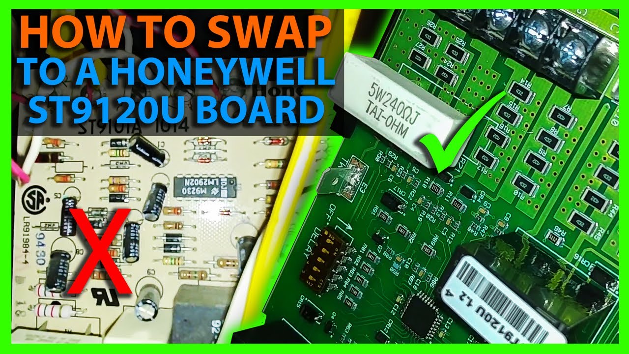
St9120u wiring diagram. The st9120u universal electronic fan timers integrate control of all combustion blower and circulating fan operations in a gas warm air appliance. This is a brand new honeywell furnace control circuit board. Mount the st9120u electronic fan timer in the appliance wiring compartment using the four provided no.

Disconnect power before making wiring connections. Take the black wire on the st9101 wiring adapter and connect to the s1 quick connect terminal on the st9120u 6. Take the black wire on the st9101 wiring adapter and connect to the l1 quick connect terminal on the st9120b,u.

1, 2, 3 and 4 for standard wiring connections. Turn off power to appliance. Going through it step by step without skipping any steps and you should be.

When installing the st9120u carefully check all appliance wires to make sure they are all connected to desired terminals at st9120u. When installing the st9120u,b, carefully check all appliance wires to make sure they are all connected to desired terminals at st9120u,b. Disconnect power before making wiring connections.

Wiring compartment using four no. Mercury 90 hp wiring diagram. Wiring caution explosion or fire hazard.

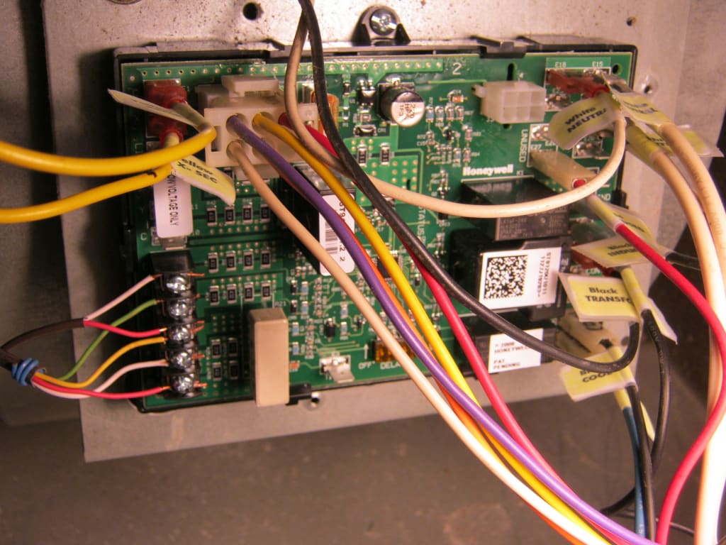
Wiring caution explosion or fire hazard. This control is the central wiring point for most of the electrical components in the furnace. The basic purposes of the st9120u are to monitor the thermostat for heat, cool and fan demands, run the.

Wiring make sure that all wiring complies with local codes and ordinances. Wiring make sure that all wiring complies with local codes and. Take the black wire on the st9101 wiring.

The wiring diagram provided by honeywell does not address on which terminals the orange wires labeled 22 and 21, these leads went to the motor lead terminals on the original controller. The fan control board in the bottom supplies 120v to the sv9541 (connector c3). Assortment of rv converter charger wiring diagram.

There is a relay on the sv9541 that controls it. When installing the st9120u, carefully check all appliance wires to make sure they are all connected to desired terminals at st9120u. Incorrect wiring can lead to explosion hazard, fire, or equipment damage.

Make sure that all wiring complies with local codes and ordinances. Ok can someone help me with the wiring diagram from a st9120c 4057 to a st9120u. Disconnect power before making wiring connections.

1 and 2 for standard wiring connections. Looking at the manual wiring diagram and looking at your furnace wiring diagram. It is approx 22 between the housings.

The linked images are printable but may print across more than 1 page in order to be legible. It's designed to replace all the honeywell part #s listed below. On the st9101 wiring adapter.

Honeywell st9120u furnace control board, honeywell, how to install amp wire the fan amp limit controls on furnaces, shop for honeywell furnace control on zoro com, how to wire. I need a wire for wire to where every wire go on new style. 3 and 4 for internal schematics.

30 amp rv plug wiring diagram inspirational wiring diagram for rv inverter best 50 amp wiring diagram ref trailer wiring diagram electrical wiring diagram wire. Identify the model number of the board being replaced and set the dip switches based on table 3. Incorrect wiring can lead to explosion hazard, fire,

The sv9541 then supplies the 120v to the combustion blower ( connector c3). A wiring diagram is a simplified standard pictorial depiction of an electrical circuit. You will only use one of wiring harnesses in the package (if you require any of them.

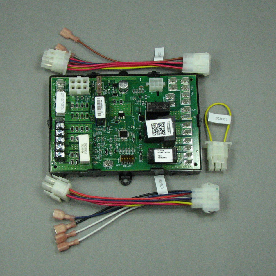
Here is the wiring diagram. Also on the circuit board the led flashes so i know something isnt right. Board comes with instructions and several wiring harnessness to convert old plug designs into this updated board.

Take the blue wire on the st9101 wiring adapter and connect to the d1 quick connect terminal on the st9120u 7. Take the blue wire on the st9101 wiring adapter and connect to the ind quick connect terminal on the st9120b,u. Wiring color codes here is a listing of common color codes for mercury and mariner us made outboard motors.

St9120b,u wiring conversion instructions 1. Some models include an enclosure. Identify the model number of the board being replaced and set the dip switches based on table 2.

The furnace is a 1993 icp Image result for wiring diagram for 1990 mercury force 120 hp outboard motor outboard motors outboard motor parts.


St9120u Wiring Diagram Complete Wiring Schemas


St9120u Wiring Diagram Complete Wiring Schemas


St9120u Wiring Diagram Complete Wiring Schemas


St9120u Wiring Diagram Complete Wiring Schemas


St9120u Wiring Diagram Complete Wiring Schemas


St9120u Wiring Diagram Complete Wiring Schemas


St9120u Wiring Diagram Complete Wiring Schemas


St9120u Wiring Diagram Complete Wiring Schemas


St9120u Wiring Diagram Complete Wiring Schemas


St9120u Wiring Diagram Complete Wiring Schemas


St9120u Wiring Diagram Complete Wiring Schemas


St9120u Wiring Diagram Complete Wiring Schemas


St9120u Wiring Diagram Complete Wiring Schemas


St9120u Wiring Diagram Complete Wiring Schemas


St9120u Wiring Diagram Complete Wiring Schemas


St9120u Wiring Diagram Complete Wiring Schemas


St9120u Wiring Diagram Complete Wiring Schemas


St9120u Wiring Diagram Complete Wiring Schemas


St9120u Wiring Diagram Complete Wiring Schemas